-
Introduction
In order to produce a lubricant micro-pitting or greased bearing fretting test, it is essential to choose specimens that have a tendency to produce these failure mechanisms. The lubricant or grease can then be assessed on the basis of its ability to prevent these forms of damage.
Generating satisfactory results with this test rig depends on choosing appropriate materials and relative hardness and surface roughness for the test specimens, then paying particular attention to the running-in procedure and subsequent test conditions.
Micro-pitting is influenced by contact pressure, material hardness, surface roughness and lubricant film thickness. Micro-pitting can occur at between 105 and 106 fatigue cycles. To produce micro-pitting, as opposed to macro-pitting, contact pressures must not exceed 1.5 GPa, with approximately 1 GPa providing the optimum balance between generation of the required failure mode and test duration.
To produce micro-pitting, λ ratios (film thickness/surface roughness) of less than 5 are required. The very low entrainment velocities generated in this test rig ensure that tests are run under boundary lubrication conditions, regardless of lubricant viscosity.
In order to achieve a uniform distribution of surface roughness, running-in must be carried out at contact pressures at the lower end of the elastic shakedown limit; typically, this should not exceed 0.25 GPa. Running-in will normally be complete after approximately 105 fatigue cycles.
Many types of rolling element bearing contacts give rise to areas of micro-slip between the rolling element and the bearing race. This is the principal mechanism contributing to frictional losses in bearings.
Fretting in grease-lubricated bearings can occur under conditions of low amplitude oscillatory motion of the bearing, resulting in micro-slip in the contact. This can result in ejection of grease from the contact and removal of protective films. This, combined with the generation and entrainment of oxide debris, can result in damage to, and premature failure of, the bearing. Greases are tested to assess their relative abilities to prevent fretting.Description
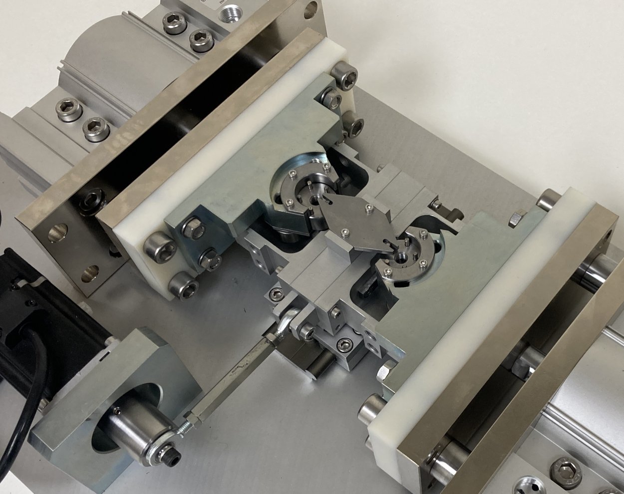
The machine comprises a reciprocating drive, with guided cylinders mounted on either side of a
reciprocating assembly. Plate specimens are mounted on either side of the reciprocating
assembly, with 20 mm roller samples loaded in contact. Load is applied through a pair of needle roller cam followers, in rolling contact with the test roller.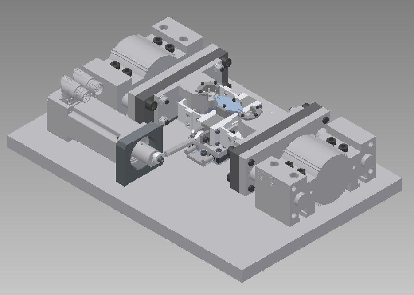
To generate variable slip in the contact between the test roller and plate specimen, a flanged carrier is pressed onto the test roller. The flange has a driving pin on its free side, with the pin PCD chosen to generate the required slide-roll behaviour. A forked plate attached to the reciprocating shaft engages with this pin. The flange also provides vertical location of the test roller.
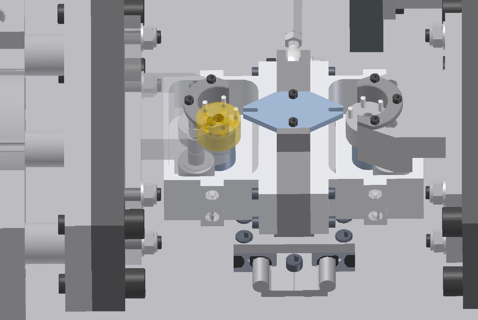
The driving pin PCD is the same as the test roller diameter. This results in pure rolling (zero slide-roll ratio) at the mid-stroke position, rising to a maximum at stroke end.
Reciprocating motion is generated by a simple gear-motor driven crank mechanism, generating a stroke amplitude of +/-1 mm for bearing fretting tests and +/-4 mm for micro-pitting tests.
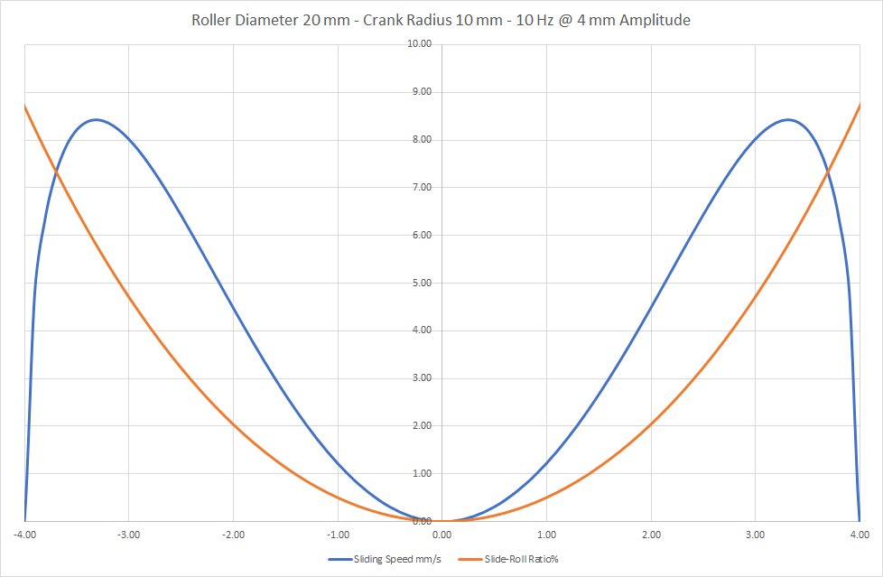
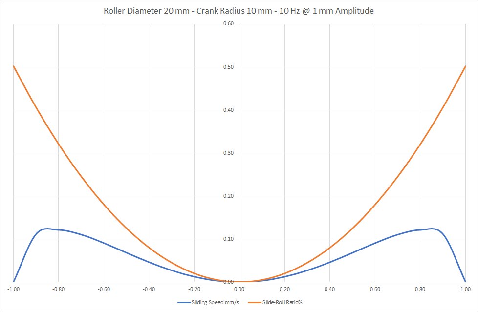
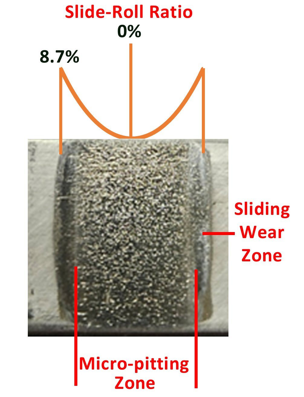
The slide-roll ratio at +/-1 mm is 0% at mid-stroke and 0.5% at stroke-end, resulting in micro-slip in the contact. At +/-4 mm, it is 0% at mid-stroke and 8.7% at stroke-end, matching the kind of slide-roll ratios associated with micro-pitting in gears.
The specimens are subjected to two fatigue cycles per reciprocating cycle, hence at 10 Hz reciprocating frequency, it takes just over seven hours to impose 500,000 fatigue cycles per specimen. As TE 55 is a two-station rig, it means that a total of 1,000,000 fatigue cycles will have been generated by the machine in that time, making it a highly efficient device for generating micro-pitting or bearing fretting wear.Variable Slide-Roll Ratio Geometry
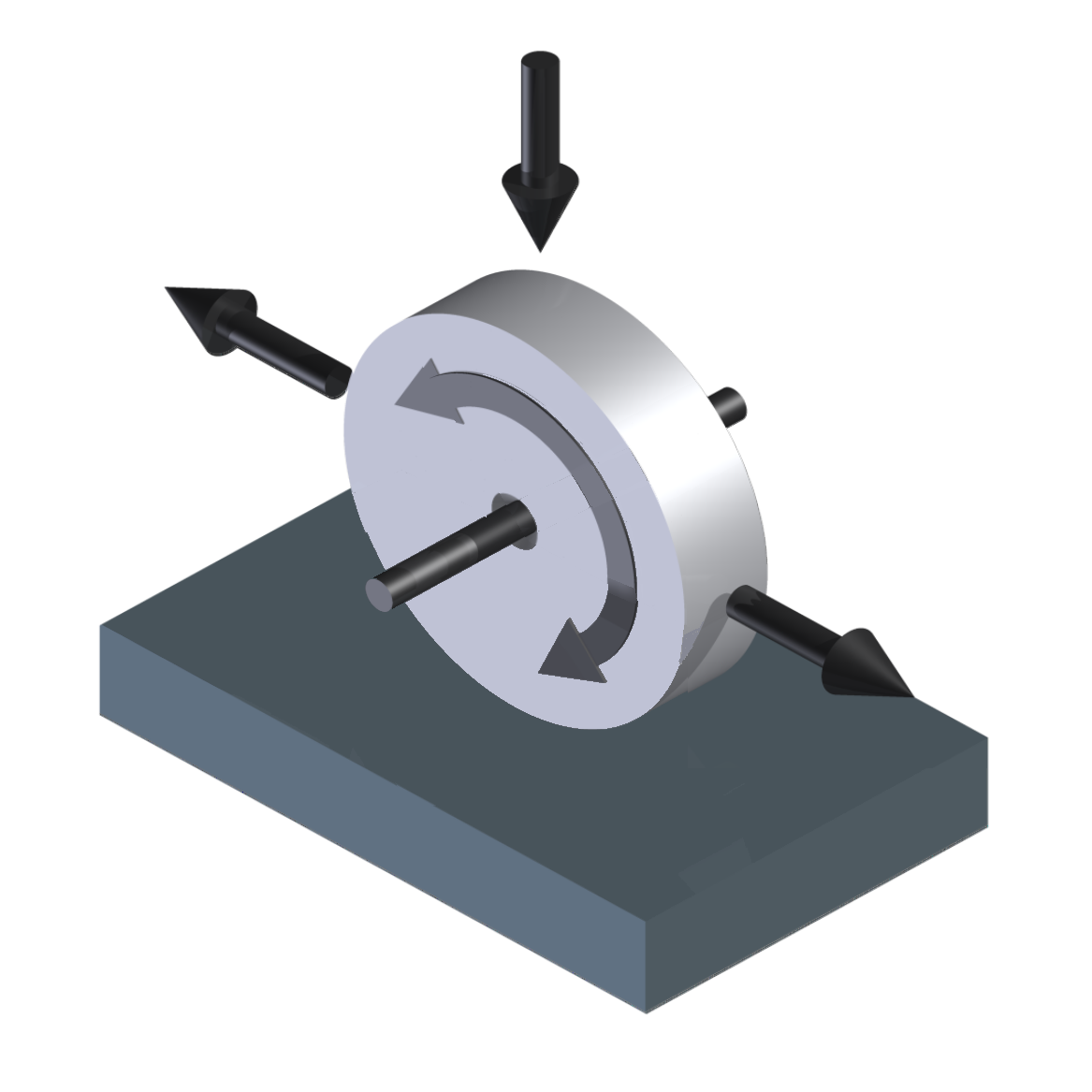
The following explains the basic mechanism for generating stroke-wise variation of slide-roll ratio.
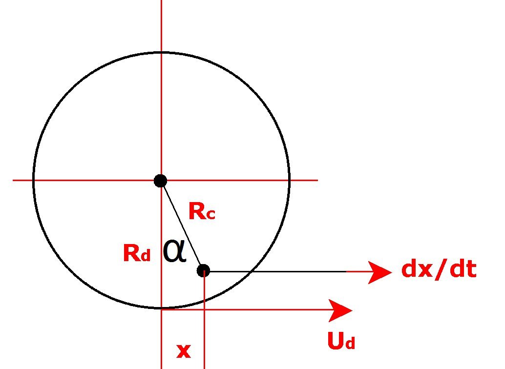
Where:
Rd = Disc radius Rc = Crank radius A = Reciprocating amplitude x = Reciprocating stroke position α = Angular rotation Ud = Disc surface speed relative to O Up = Plate surface speed relative to O Slide Roll Ratio = Sliding Velocity / Rolling Velocity Sliding Velocity = |Ud – Up| Rolling Velocity = 0.5 . (Ud + Up) Slide Roll Ratio % = 200 x |Ud – Up| / (Ud + Up) Up = dx/dt = A ω Cos ωt Ud = Rd . dα/dt Geometry:
Sin α = x / Rc α = Sin-1 (x / Rc) dα/dt = dx/dt . (Rc2 – x2)-0.5 Hence:
Ud = [Rd . (Rc2 – x2)-0.5] . dx/dt Slide Roll Ratio % = 200 x |Ud – Up| / (Ud + Up) = 200 x |[Rd . (Rc2 – x2)-0.5] . dx/dt – dx/dt| / [[Rd . (Rc2 –x2)-0.5] . dx/dt + dx/dt] = 200 x |[Rd . (Rc2 – x2)-0.5] – 1| / [[Rd . (Rc2 – x2)-0.5] + 1] With Disc Radius (Rd) = Crank radius (Rc) = 20 mm, the slide-roll ratio and sliding speed vary with stroke position as shown below:
It is possible to make small adjustments to the Crank Radius of PCD +/-0.5 mm. In this case the
slide-roll ratio at mid-stroke is not zero, but note that the sliding at mid-stroke will be in opposite
directions, depending on whether the Crank Radius is greater or lesser than the PCD.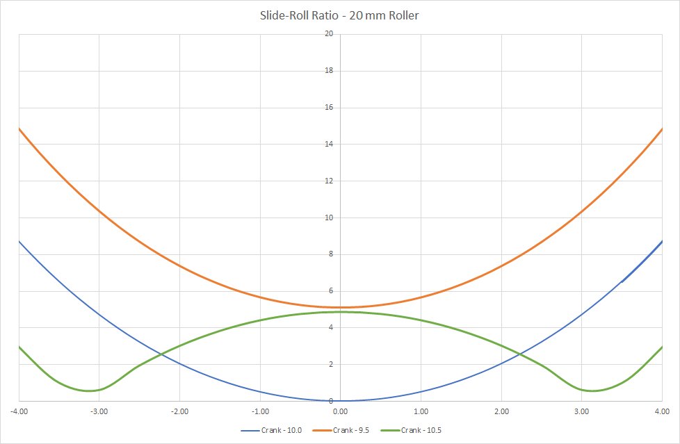
Example Test – Micro-pitting
This example test was run with PAO4 at 10 Hz and, after running-in, 1.0 GPa contact pressure. Test plates taken direct from the machine look like this:
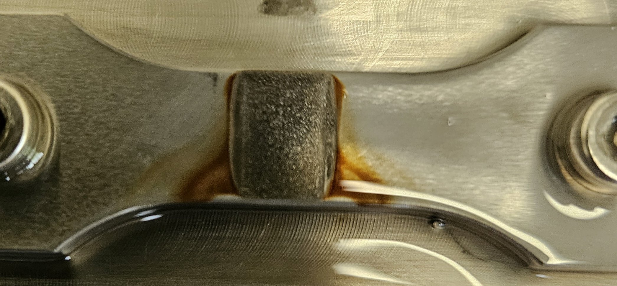
After 600,000 reciprocating cycles, in other words, 1,200,000 fatigue cycles, the specimen surfaces look like this:
After 1,500,000 fatigue cycles they look like this:
At the stroke ends, where the slide-roll ratio reaches a maximum, micro-pitting gives way to plastic deformation and sliding wear.
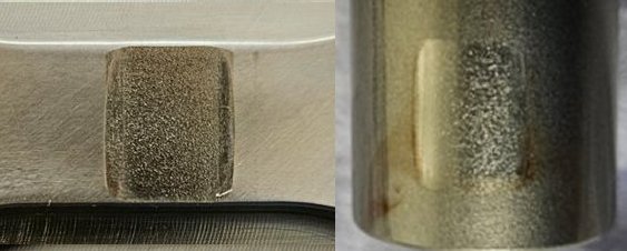
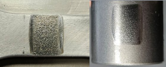
Example Test – Bearing Fretting
These example tests were run with two different greases, at 10 Hz and 2 mm stroke. After running-in, the tests were run at a contact pressure of 0.75 GPa for 200,000 reciprocating cycles generating 400,000 fatigue Cycles.
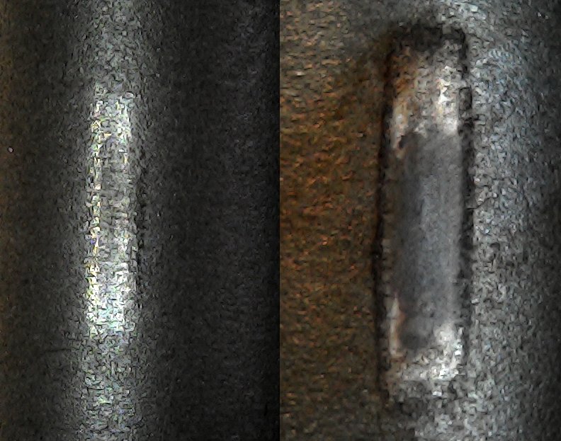
Comparing the two rolling element test specimens, the grease used for the right-hand test resulted in much more wear than the left-hand test, with significant evidence of a build-up in oxide debris.
Control and Instrumentation
The rig has a PLC controller which provides a programmable batch counter function (for programming the required number of cycles) and a PID controller for temperature control. On-screen functions allow manual control of motor speed and display of load, temperature, frequency and number of cycles.
Standard Test Specimens
Micro-pitting Test:
Hardened NSOH BO1 tool steel roller on annealed 52100 plate
Bearing Fretting Tests:
52100 Bearing Roller on annealed 52100 plate -
TE 55 MICRO-PITTING & BEARING FRETTING RIG
Technical Specifications
Contact Configuration: Roller on Flat Roller Diameter: 20 mm Flat Width: 5 to 10 mm Amplitude – Fretting Tests: +/-1 mm Slide-Roll Ratio – Fretting Tests: 0% at mid-stroke – 0.5% at stroke-end Amplitude – Micro-Pitting Tests: +/-4 mm Slide-Roll Ratio – Micro-Pitting Tests: 0% at mid-stroke – 8.7% at stroke-end Load Actuator: Pneumatic Cylinder – 80 mm Diameter Load Measurement: Pressure Transducer with PLC display Contact Pressures (steel): Pressure (Bar) Pmax GPa – 10 mm wide contact 1.00 0.43 2.00 0.61 3.00 0.75 4.00 0.86 5.00 0.96 5.40 1.00 6.00 1.06 7 1.14 Temperature Range: Ambient to 80°C Motor and Drive: Single Phase 400 W Gear-motor Maximum Frequency: 10 Hz Controller: PLC with touch-screen user interface Manually Controlled Parameters
Load – Manual Pressure Regulator Rotational Speed – PLC Automatically Controlled Parameters
Reservoir Temperature – PID Control – PLC Test Duration – Batch Counter – PLC Services
Electricity: 220/240V, single phase, 50 Hz, 1.2 kW 110/120 V, single phase, 60 Hz, 1.2 kW Compressed Air: 4 cfm at 8 bar (typical) -
Overview Videos
-
Index Tags
-